
An ESP32 camera adds Wi-Fi to a blood-pressure display by reading its digits
The hobby build uses a fixed mount and manually mapped segments, with a wiring-free route distinct from its optional sleep circuit.
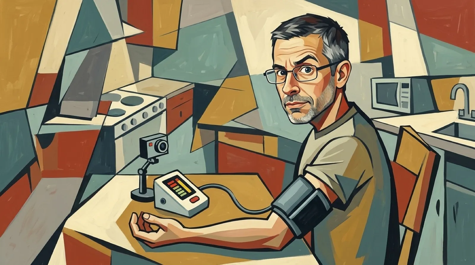
The blood-pressure monitor already knows the reading. Getting that number onto a network usually means replacing the monitor or opening it. This build adds a third option: point a camera at the screen and let the digits speak for themselves (no new cuff required).
The maker’s project uses an ESP32-CAM to read systolic pressure, diastolic pressure, and pulse from a seven-segment display. It copies the screen rather than measuring blood pressure. That boundary matters more than any smart label somebody could stick on the case.
The build started around an A&D UA-611 monitor. A supplied printable arm holds the camera in front of that model. Another monitor needs a suitable mount and mapping of its display. The software can’t infer that your particular screen is arranged differently because both boxes say blood pressure.
The workflow has three stages. First comes a live camera preview and a saved frame. A desktop mapper then places boxes around each digit’s segments. The resulting map goes into the reader firmware, which detects the lit pattern and converts the result into numbers.
That makes camera position part of the configuration. Move it after mapping and the boxes can sample different pixels. A fixed mount is doing real computational work by preventing the software’s assumptions from wandering off with the camera. Even a very clever parser appreciates a subject that sits still.
Play the video on YouTubeThe README includes adjustments for uncertain segment readings and a debug page showing individual segments. Lighting and glare can change what looks lit. A number arriving as valid JSON therefore tells you it traveled successfully; it doesn’t establish that the camera read the original display correctly.
HTTP POST sends the user label and three readings to a configured destination. The maker gives Home Assistant webhook and Node-RED examples. That turns the output into something a home system can receive without giving the monitor itself a new network stack or a vendor account with a password-recovery adventure.
The wiring distinction needs to stay visible. The basic external setup requires no wires into the monitor. An optional deep-sleep arrangement uses its start-button line, and the original video’s power arrangement also taps internal wiring. Those are extra modifications; they shouldn’t sneak into a promise that the whole project always leaves the case closed.
The project’s disclaimer is equally direct about the hobby reader being able to misread. Any important transcription needs checking against the monitor. This is an account of a data-copying build, with no claim of medical validation or guidance for interpreting readings.
The broader technique could make other fixed, segmented displays readable by systems they were never designed to join. Each screen would still need its own geometry and lighting check. The clever economy is using an instrument’s finished display, while leaving the reliability of that copied number as an explicit engineering job.
The cuff keeps its day job.